Baughman Tile products shall be installed according to ASTM D2321, Standard Practice for Underground Installation of Thermoplastic Pipe for Sewers and Other Gravity-Flow Applications. By carefully following these installation guidelines, you will achieve an easy to install, safe, long lasting and functional Baughman Tile drainage system.
Please pay special attention to all required safety regulations; including but not limited to The Department of Labor, Occupational Safety and Health Administration (OSHA), Safety and Health Regulations for Construction during installation of the drainage system. There are specific safety guidelines required during construction including foundation preparation, excavation, pipe handling, assembly and backfilling. Please refer to your specific state and local jurisdictions for more detail.
The below installation tips will be helpful for review:
1. Care during installation
Care should be be taken to prevent damage to the tubing during the backfilling operation. Avoid dropping large soil clods or rocks directly on the tubing. Heavy loads of all types should be avoided until the soil around the installation area is properly settled.
2. Bedding
Tubing should be bedded in gravel. In some situations, customers choose not to use the required gravel backfill, and instead elect to use a soil backfill material such as crushed stone or compacted soil and are still able to achieve satisfactory results. The bedding material should be placed around the tubing to a depth at least 2” over the top of the tubing. When selected soil bedding material from the trench excavation is used, choose small loose particles of soil that will flow around the tubing and minimize soil settling. Avoid large rocks that may damage the tubing or large clods of soil that cause voids and subsequent excessive settling.
3. Depth of cover
If vehicular traffic is expected over tubing, there should be a minimum of 12” of cover over tubing if gravel bedding material is used and 24” of cover if selected soil bedding material is used. Typical recommended gravel materials are pea gravel, GA stone or pit run course sand and gravel mixes.
4. Proper grade
The grade, or fall, on which tubing is laid is important in that reversals in grade will reduce the effectiveness of the system. Best drainage results are achieved with a continuous downhill fall, or grade, over the entire length of the drain line. A fall of 0.2 inches per 10 feet of length is generally considered adequate. Greater fall will promote more rapid drainage.
5. Proper selection of Baughman Tile materials
Choose your materials according to application. If absorption and drainage are required, perforated tubing should be used. If tubing serves only to move water away from area (such as downspout run-offs, etc), non-perforated tubing is best because it will not dissipate water into the surrounding area. Non-perforated tubing should also be used if the line runs close to trees where root penetration may be a problem. If the soil being drained is sandy and silty, then either Poly-Drain® protective wrap or gravel should be used to prevent the soils from entering and blocking the drainage line.
6. Minimum Trench Width
Minimum trench width is a function of pipe diameter, backfill material, and the compaction technique. The minimum trench width must accommodate the pipe and compaction equipment, if used, on both sides of the pipe. In actual application, the trench width also may be influenced by the equipment the contractor has available. From the early days, typical trench widths have been twice the nominal diameter, but never more than the nominal diameter plus 2′ (0.6m). AASHTO Section 30 requires a minimum trench width of not less than 1.5 times the pipe outside diameter plus 12 in. (300 mm). ASTMD 2321 establishes trench widths as the greater of either the pipe outside diameter plus 16 in. (400 mm) or 1.25 times the pipe outside diameter plus 12 in. (300 mm). The chart below outlines the ASTM & AASHTO recommendations.
| Inside Diameter in. | Approximate Outside Diameter in. | AASHTO Sec 30 Min. Trench Width in. | ASTM D 2321 Min. Trench Width in. |
|---|---|---|---|
| 4 | 4.75 | 19 | 21 |
| 6 | 6.98 | 22 | 23 |
| 8 | 9.50 | 26 | 26 |
| 10 | 11.80 | 30 | 28 |
| 12 | 14.50 | 34 | 31 |
| 15 | 18.00 | 39 | 35 |
| 18 | 21.50 | 44 | 39 |
| 24 | 28.50 | 55 | 48 |
| 30 | 35.65 | 65 | 57 |
| 36 | 42.50 | 76 | 65 |
| 42 | 48.20 | 84 | 72 |
| 48 | 54.30 | 93 | 80 |
| 60 | 67.00 | 113 | 96 |
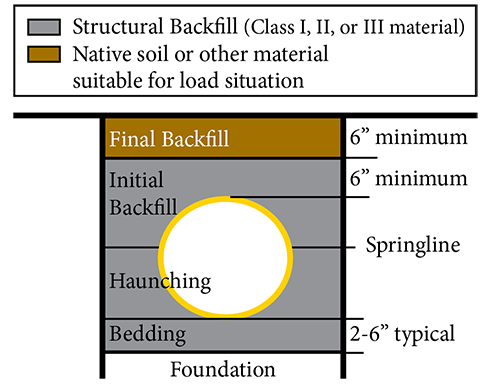
7. The Backfill Envelope
- The backfill envelope can be considered to have specific zones, each having a specific purpose.
Bedding provides a uniform base to ensure that grade is maintained and that loads can be distributed into the foundation - Haunching extends from the bedding to the pipe springline, or midpoint. This section of the backfill performs primarily by resisting applied loads.
- Initial backfill, situated above the springline to a point at least 6″ above the crown, supports loads on either side of the pipe.
- Final backfill helps distribute surface-applied loads. The height of the initial and final backfill areas should be at least 1′ over the pipe crown in installations involving maximum loads of AASHTO H-20 or HS-25.Higher backfill amounts are needed for larger diameter pipes and some soil types.
Bedding, haunching, and initial backfill provide strength to the system; they must consist of an appropriate backfill material and be compacted, if required. Final backfill does not directly provide support to the pipe; it usually can consist of excavated trench material or another material suitable for the expected loads. Additional information regarding appropriate backfill materials and recommended compaction levels is included in the CPPA technical booklet and can be found in ASTM D2321.